Get in touch!
Alternatively, you can contact us like this:
If you're not sure which product you need, try our Quick Product Finder
Ways to avoid cross-connection of remote sense wires
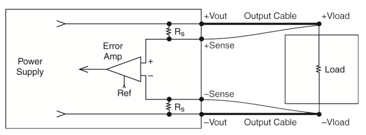
It is important to ensure the correct polarities of the power supply are use in the remote sense circuit; the +ve sense wire should connect at the load near the +ve Vload connection, and the –ve sense wire to the -ve Vload connection.
Simplified schematic of remote sense circuit with external output and sense wires
If the remote sense wires are crossed-connected (i.e. +ve sense to –Vload and –ve sense to +Vload), current will flow in the sense lines and ultimately this will burn out the internal R-sense resistors, causing the power supply to malfunction.
Typically, these internal R-sense resistors are around 10 to 100 Ohms with a maximum rating of 0.5W.
Simplified schematic of remote sense circuit with external output and sense wires